VINTAGE OWNER'S MANUALS, SERVICE MANUALS, BROCHURES AND PUBLICATIONS
Welcome to Automatic Ephemera, a library for historical research and education, sharing public domain documents relating to vintage products for
the home. You are viewing the low-resolution preview, high-resoultion versions are also available for most documents.
The scanning of all high-resolution documents is done at 300dpi with the utmost diligence and care to produce high quality .pdf files which have text
search capabilities built-in to bring modern convenience to vintage printed materials.
The high resolution also allows for close-up examination of all images on your computer monitor and in many cases makes
reading the text easier than the original document. Quality printers can print these documents nearly identically to the original document. Maintaining a library as such is a
time consuming and expensive venture, all materials have a small download fee to offset the library's many expenses.
In order to read these documents you need Adobe
Reader 7 or greater installed on your computer. Click here for samples of the Documents in our library.
If you have had any recent download purchases please see your download page.
If you have had any recent download purchases please see your download page.
1959 Frigidaire Dryer Service Tech-Talk (continued)
Page 19 of 32 First Page
< Back (Page 18)
> Next (Page 20)
...
Last (Page 32)
You are viewing a low-resolution preview. Available here is the high-res/32 page PDF version of this document ($2.64), most printers can output this nearly identically to the original document.

Automated Summary of Text on this Page:
THERMOSTAT MOUNTING SCREWS
CONTROL PLATE
INDICATOR AND GUIDE MOUNTING SCREWS
INDICATOR SLIDE
INDICATOR DRIVE PULLEY
CORD
EYELET
SPRING
INDICATOR IDLER PULLEY
EYELET
PULLEY MOUNTING SCREW
INDICATOR AND GUIDE ASSEMBLY
EYELET
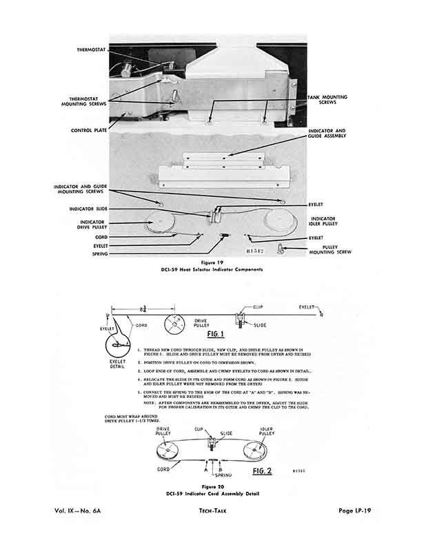
Figure 1 9
DCI-59 Heat Selector Indicator Components
EYELET 2. POSITION DRIVE PULLEY ON CORD TO DIMENSION SHOWN.
DETAIL
3. LOOP ENDS OF CORD, ASSEMBLE AND CRIMP EYELETS TO CORD AS SHOWN IN DETAIL.
4. RELOCATE THE SLIDE IN ITS GUIDE AND FORM CORD AS SHOWN IN FIGURE 2. (GUIDE AND IDLER PULLEY WERE NOT REMOVED FROM THE DRYER)
5. CONNECT THE SPRING TO THE ENDS OF THE CORD AT "A" AND "B" . (SPRING WAS REMOVED AND MUST BE REUSED)
NOTE: AFTER COMPONENTS ARE REASSEMBLED TO THE DRYER, ADJUST THE SLIDE FOR PROPER CALIBRATION IN ITS GUIDE AND CRIMP THE CLIP TO THE CORD.
CORD MUST WRAP AROUND DRIVE PULLEY 1-1/2 TIMES.
Figure 20
DCI-59 Indicator Cord Assembly Detail
You are viewing a low-resolution preview. Available here is the high-res/32 page PDF version of this document ($2.64), most printers can output this nearly identically to the original document.

Automated Summary of Text on this Page:
THERMOSTAT MOUNTING SCREWS
CONTROL PLATE
INDICATOR AND GUIDE MOUNTING SCREWS
INDICATOR SLIDE
INDICATOR DRIVE PULLEY
CORD
EYELET
SPRING
INDICATOR IDLER PULLEY
EYELET
PULLEY MOUNTING SCREW
INDICATOR AND GUIDE ASSEMBLY
EYELET
Figure 1 9
DCI-59 Heat Selector Indicator Components
EYELET 2. POSITION DRIVE PULLEY ON CORD TO DIMENSION SHOWN.
DETAIL
3. LOOP ENDS OF CORD, ASSEMBLE AND CRIMP EYELETS TO CORD AS SHOWN IN DETAIL.
4. RELOCATE THE SLIDE IN ITS GUIDE AND FORM CORD AS SHOWN IN FIGURE 2. (GUIDE AND IDLER PULLEY WERE NOT REMOVED FROM THE DRYER)
5. CONNECT THE SPRING TO THE ENDS OF THE CORD AT "A" AND "B" . (SPRING WAS REMOVED AND MUST BE REUSED)
NOTE: AFTER COMPONENTS ARE REASSEMBLED TO THE DRYER, ADJUST THE SLIDE FOR PROPER CALIBRATION IN ITS GUIDE AND CRIMP THE CLIP TO THE CORD.
CORD MUST WRAP AROUND DRIVE PULLEY 1-1/2 TIMES.
Figure 20
DCI-59 Indicator Cord Assembly Detail
Page 19 of 32