VINTAGE OWNER'S MANUALS, SERVICE MANUALS, BROCHURES AND PUBLICATIONS
Welcome to Automatic Ephemera, a library for historical research and education, sharing public domain documents relating to vintage products for
the home. You are viewing the low-resolution preview, high-resoultion versions are also available for most documents.
The scanning of all high-resolution documents is done at 300dpi with the utmost diligence and care to produce high quality .pdf files which have text
search capabilities built-in to bring modern convenience to vintage printed materials.
The high resolution also allows for close-up examination of all images on your computer monitor and in many cases makes
reading the text easier than the original document. Quality printers can print these documents nearly identically to the original document. Maintaining a library as such is a
time consuming and expensive venture, all materials have a small download fee to offset the library's many expenses.
In order to read these documents you need Adobe
Reader 7 or greater installed on your computer. Click here for samples of the Documents in our library.
If you have had any recent download purchases please see your download page.
If you have had any recent download purchases please see your download page.
1959 Frigidaire Dryer Service Tech-Talk (continued)
Page 10 of 32 First Page
< Back (Page 9)
> Next (Page 11)
...
Last (Page 32)
You are viewing a low-resolution preview. Available here is the high-res/32 page PDF version of this document ($2.64), most printers can output this nearly identically to the original document.

Automated Summary of Text on this Page:
Use either 3/4z rigid conduit or armored cable or, preferably, a standard range cord and plug assembly (pigtail).
When using a pigtail, a suitable 3-wire receptacle should be mounted on the wall adjacent to the dryer, readily accessible to the user.
If rigid conduit or armored cable is used, the branch circuit must be provided with an approved 30 ampere switch at the distribution panel or at the dryer.
The Cabinet Must Be Grounded-A grounding strap is attached to each terminal block bracket. If it is desired to use the strap for grounding purposes, the free end of the strap must be attached to the center terminal. If a separate grounding wire is required, a No. 14 AWG wire with solderless connector can be attached to the screw provided on the terminal block bracket and then run to an approved grounding electrode such as a cold water pipe.
DD-59, DCD-59, DI-59 and DCI-59 Models Converted to 120 Volt Operation:
(120 Volt, 2-wire separate branch circuit fused for 20 amperes.)
All dryers can be converted to 2-wire, 120 volt operation by changing the Red lead at the terminal block from the Red to the White terminal and by using Cord Package No. 5876843 for connecting the dryer to the source of
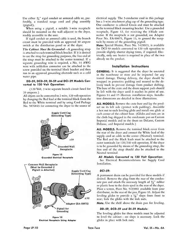
Common Wall Receptacle (Must be Grounded if Pigtail is Attached)
Supply Cord Cap (Grounding Type)
A50
Adapter (EA-99675)
Pigtail for Grounding
Figure 1 3 Electrical Receptacle Using Adapter
electrical supply. The 3-conductor cord in this package has a 3-wire attachment plug cap of the grounding type. One conductor is colored Green and must be attached to the terminal block mounting bracket. Use a grounded receptacle, Figure 12, for receiving the 3-blade connector. If the receptacle is not grounded, use Adapter Piece No. EA-99675, Figure 13, to ground the receptacle by means of the grounding pigtail.
Note: Special Heater, Piece No. 5429923, is available for DCI-59 models converted to 120 volt operation to provide slightly shorter drying times, if required. Electrically, only one heater is required in place of the two already on the product.
Installation Instructions
GENERAL: It is suggested that the dryer be uncrated in the warehouse or store and be inspected for any transit damage. During delivery, the dryer should be wrapped in protective padding and secured to the delivery truck to prevent damage from product shifting. The base of the crate and the drum support pads should be left with the dryer until it reaches its point of use. Figures 14 and 15 illustrate installation steps. Installation dimensions are detailed in these illustrations.
ALL MODELS: Remove the crate base and lay the product on its left side (protect with padding). Assemble a hex nut to each leveling glide and install one glide at each corner of the cabinet base. (Glides and nuts are in the cloth bag shipped in the condensate pan on Custom Imperial models and in the drum on DeLuxe, Custom DeLuxe, and Imperial models.)
ALL MODELS: Remove the terminal block cover from the rear of the dryer and connect the White lead of the supply cord or cable to the center (Neutral) terminal. The Red and the Black leads must be attached to the outer terminals for 120/240 volt operation. If the dryer is to be grounded by means of the grounding strap, the free end of the strap should also be attached to the Neutral terminal.
All Models Converted to 120 Volt Operation:
See Electrical Recommendations for Supply Cord Installation.
DCI-59:
A permanent drain can be provided for these models if desired. Remove the plug from the rear of the condensate pan and attach the necessary length of rubber or plastic hose to the drain spud in the rear of the dryer. Place a screen, Piece No. 5433861 available from your distributor, in the rear of the pan, Figure 35. Adjust the leveling glides to provide a y8" slope from front to rear; lock the glides with the lock nuts.
Note: Use the shelf above the drain pan for leveling.
DD-59, DCD-59 and DI-59 Models:
The leveling glides for these models must be adjusted to level the cabinet-no slope is necessary. Lock the glides in place with lock nuts.
Supply Cord Cap (Grounding Type)
A50
Grounded Wall Receptacle
Figure 1 2 Grounded Electrical Receptacle
You are viewing a low-resolution preview. Available here is the high-res/32 page PDF version of this document ($2.64), most printers can output this nearly identically to the original document.

Automated Summary of Text on this Page:
Use either 3/4z rigid conduit or armored cable or, preferably, a standard range cord and plug assembly (pigtail).
When using a pigtail, a suitable 3-wire receptacle should be mounted on the wall adjacent to the dryer, readily accessible to the user.
If rigid conduit or armored cable is used, the branch circuit must be provided with an approved 30 ampere switch at the distribution panel or at the dryer.
The Cabinet Must Be Grounded-A grounding strap is attached to each terminal block bracket. If it is desired to use the strap for grounding purposes, the free end of the strap must be attached to the center terminal. If a separate grounding wire is required, a No. 14 AWG wire with solderless connector can be attached to the screw provided on the terminal block bracket and then run to an approved grounding electrode such as a cold water pipe.
DD-59, DCD-59, DI-59 and DCI-59 Models Converted to 120 Volt Operation:
(120 Volt, 2-wire separate branch circuit fused for 20 amperes.)
All dryers can be converted to 2-wire, 120 volt operation by changing the Red lead at the terminal block from the Red to the White terminal and by using Cord Package No. 5876843 for connecting the dryer to the source of
Common Wall Receptacle (Must be Grounded if Pigtail is Attached)
Supply Cord Cap (Grounding Type)
A50
Adapter (EA-99675)
Pigtail for Grounding
Figure 1 3 Electrical Receptacle Using Adapter
electrical supply. The 3-conductor cord in this package has a 3-wire attachment plug cap of the grounding type. One conductor is colored Green and must be attached to the terminal block mounting bracket. Use a grounded receptacle, Figure 12, for receiving the 3-blade connector. If the receptacle is not grounded, use Adapter Piece No. EA-99675, Figure 13, to ground the receptacle by means of the grounding pigtail.
Note: Special Heater, Piece No. 5429923, is available for DCI-59 models converted to 120 volt operation to provide slightly shorter drying times, if required. Electrically, only one heater is required in place of the two already on the product.
Installation Instructions
GENERAL: It is suggested that the dryer be uncrated in the warehouse or store and be inspected for any transit damage. During delivery, the dryer should be wrapped in protective padding and secured to the delivery truck to prevent damage from product shifting. The base of the crate and the drum support pads should be left with the dryer until it reaches its point of use. Figures 14 and 15 illustrate installation steps. Installation dimensions are detailed in these illustrations.
ALL MODELS: Remove the crate base and lay the product on its left side (protect with padding). Assemble a hex nut to each leveling glide and install one glide at each corner of the cabinet base. (Glides and nuts are in the cloth bag shipped in the condensate pan on Custom Imperial models and in the drum on DeLuxe, Custom DeLuxe, and Imperial models.)
ALL MODELS: Remove the terminal block cover from the rear of the dryer and connect the White lead of the supply cord or cable to the center (Neutral) terminal. The Red and the Black leads must be attached to the outer terminals for 120/240 volt operation. If the dryer is to be grounded by means of the grounding strap, the free end of the strap should also be attached to the Neutral terminal.
All Models Converted to 120 Volt Operation:
See Electrical Recommendations for Supply Cord Installation.
DCI-59:
A permanent drain can be provided for these models if desired. Remove the plug from the rear of the condensate pan and attach the necessary length of rubber or plastic hose to the drain spud in the rear of the dryer. Place a screen, Piece No. 5433861 available from your distributor, in the rear of the pan, Figure 35. Adjust the leveling glides to provide a y8" slope from front to rear; lock the glides with the lock nuts.
Note: Use the shelf above the drain pan for leveling.
DD-59, DCD-59 and DI-59 Models:
The leveling glides for these models must be adjusted to level the cabinet-no slope is necessary. Lock the glides in place with lock nuts.
Supply Cord Cap (Grounding Type)
A50
Grounded Wall Receptacle
Figure 1 2 Grounded Electrical Receptacle
Page 10 of 32