VINTAGE OWNER'S MANUALS, SERVICE MANUALS, BROCHURES AND PUBLICATIONS
Welcome to Automatic Ephemera, a library for historical research and education, sharing public domain documents relating to vintage products for
the home. You are viewing the low-resolution preview, high-resoultion versions are also available for most documents.
The scanning of all high-resolution documents is done at 300dpi with the utmost diligence and care to produce high quality .pdf files which have text
search capabilities built-in to bring modern convenience to vintage printed materials.
The high resolution also allows for close-up examination of all images on your computer monitor and in many cases makes
reading the text easier than the original document. Quality printers can print these documents nearly identically to the original document. Maintaining a library as such is a
time consuming and expensive venture, all materials have a small download fee to offset the library's many expenses.
In order to read these documents you need Adobe
Reader 7 or greater installed on your computer. Click here for samples of the Documents in our library.
If you have had any recent download purchases please see your download page.
If you have had any recent download purchases please see your download page.
1959 Frigidaire Dryer Service Tech-Talk (continued)
Page 24 of 32 First Page
< Back (Page 23)
> Next (Page 25)
...
Last (Page 32)
You are viewing a low-resolution preview. Available here is the high-res/32 page PDF version of this document ($2.64), most printers can output this nearly identically to the original document.

Automated Summary of Text on this Page:
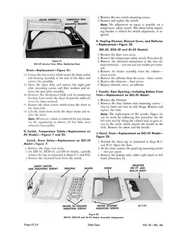
ASSEMBLY-l THERMOSTAT BULB
AND
MOUNTING BRACKETS
Figure 31
DCI-59 Interior View When Replacing Drum
Drum - Replacement - Figure 3 7:
14. Loosen the two screws which secure the lamp socket and housing assembly at the rear of the dryer and remove the assembly.
15. Open the dryer door and remove the eight port plate mounting screws and fiber washers and remove the port plate assembly.
16. Remove the thermostat bulb and its mounting brackets from inside the dryer to provide sufficient room for drum removal.
17. Remove the three screws which secure the drum to the drum hub.
18. Lift the drum from inside the dryer frame and replace the drum.
Note: Whenever a drum is removed for any reason, use the opportunity to remove all lint from areas otherwise inaccessible.
G. Switch, Temperature Safety - Replacement on
All Models - Figures 7 and 23:
Switch, Drum Safety - Replacement on DCI-59
Model - Figure 7:
1. Remove the dryer rear cover.
2. On DD-59, DCD-59, and DI-59 models, partially remove the top as instructed in Steps C-5 and D-8.
3. Remove the electrical leads from the switch.
4. Remove the two switch mounting screws.
5. Remove and replace the switch.
Note: No adjustment or repair is possible on a temperature safety switch. The drum safety mounting bracket is slotted for switch adjustment, if required.
H. Heating Element, Element Cover, and Reflector - Replacement-Figure 32:
(DD-59, DCD-59 and DI-59 Models)
1. Remove the dryer rear cover.
2. Remove the temperature safety switch, Procedure G.
3. Remove the electrical connections at the two element terminals-one nut and one washer per terminal.
4. Remove the heater assembly from the cabinet- seven screws.
5. Remove the reflector from the cover-three screws.
6. Remove the elements-four screws.
7. Replace element, cover, or reflector.
I. Treadle, Door Opening - Including Bottom Front Trims -Replacement on DCI-59 Model:
1. Remove the Filtrator.
2. Remove the four bottom trim mounting screws- two on front and two on side flange. Remove and replace the trim.
Note: The replacement of the treadle, Figure 33, can be made by following this procedure for the left trim and by tilting the cabinet back to gain access to the screw which mounts the treadle to the slide. Remove the serew and the treadle.
J. Panel, Front-Replacement on DCI-59 Model - Figure 33:
1. Position the dryer top as instructed in Steps B-21 and B-22. Open the door.
2. At the front, remove the panel top mounting screws -two per panel.
3. Remove the bottom trim, either right hand or left hand (Procedure I).
SAFETY SWITCH AND MOUNTING SCREWS HOUSING
HEATER
SHIELD
REFLECTOR (DD-59 AND DCD-59 ONLY)
B1541
HEATER TO HOUSING MOUNTING SCREWS
HEATER MOUNTING SCREWS
Figure 32
DD-59, DCD-59 and DI-59 Heater Assembly Components
You are viewing a low-resolution preview. Available here is the high-res/32 page PDF version of this document ($2.64), most printers can output this nearly identically to the original document.

Automated Summary of Text on this Page:
ASSEMBLY-l THERMOSTAT BULB
AND
MOUNTING BRACKETS
Figure 31
DCI-59 Interior View When Replacing Drum
Drum - Replacement - Figure 3 7:
14. Loosen the two screws which secure the lamp socket and housing assembly at the rear of the dryer and remove the assembly.
15. Open the dryer door and remove the eight port plate mounting screws and fiber washers and remove the port plate assembly.
16. Remove the thermostat bulb and its mounting brackets from inside the dryer to provide sufficient room for drum removal.
17. Remove the three screws which secure the drum to the drum hub.
18. Lift the drum from inside the dryer frame and replace the drum.
Note: Whenever a drum is removed for any reason, use the opportunity to remove all lint from areas otherwise inaccessible.
G. Switch, Temperature Safety - Replacement on
All Models - Figures 7 and 23:
Switch, Drum Safety - Replacement on DCI-59
Model - Figure 7:
1. Remove the dryer rear cover.
2. On DD-59, DCD-59, and DI-59 models, partially remove the top as instructed in Steps C-5 and D-8.
3. Remove the electrical leads from the switch.
4. Remove the two switch mounting screws.
5. Remove and replace the switch.
Note: No adjustment or repair is possible on a temperature safety switch. The drum safety mounting bracket is slotted for switch adjustment, if required.
H. Heating Element, Element Cover, and Reflector - Replacement-Figure 32:
(DD-59, DCD-59 and DI-59 Models)
1. Remove the dryer rear cover.
2. Remove the temperature safety switch, Procedure G.
3. Remove the electrical connections at the two element terminals-one nut and one washer per terminal.
4. Remove the heater assembly from the cabinet- seven screws.
5. Remove the reflector from the cover-three screws.
6. Remove the elements-four screws.
7. Replace element, cover, or reflector.
I. Treadle, Door Opening - Including Bottom Front Trims -Replacement on DCI-59 Model:
1. Remove the Filtrator.
2. Remove the four bottom trim mounting screws- two on front and two on side flange. Remove and replace the trim.
Note: The replacement of the treadle, Figure 33, can be made by following this procedure for the left trim and by tilting the cabinet back to gain access to the screw which mounts the treadle to the slide. Remove the serew and the treadle.
J. Panel, Front-Replacement on DCI-59 Model - Figure 33:
1. Position the dryer top as instructed in Steps B-21 and B-22. Open the door.
2. At the front, remove the panel top mounting screws -two per panel.
3. Remove the bottom trim, either right hand or left hand (Procedure I).
SAFETY SWITCH AND MOUNTING SCREWS HOUSING
HEATER
SHIELD
REFLECTOR (DD-59 AND DCD-59 ONLY)
B1541
HEATER TO HOUSING MOUNTING SCREWS
HEATER MOUNTING SCREWS
Figure 32
DD-59, DCD-59 and DI-59 Heater Assembly Components
Page 24 of 32